We all know that CNC inserts failure and its adverse impact on production equipment are similar to athletes wearing a pair of high-quality running shoes. Just as shoes withstand the weight of athletes, inserts are repeatedly subjected to tremendous stress, resulting in wear and tear. If it is not resolved, wear and tear will cause athletes to feel pain and will reduce the manufacturer’s processing accuracy and productivity.
However, carbide inserts manufacturers can analyze the tools used to maximize tool life and predict tool use, thereby maintaining part accuracy and reducing equipment performance degradation. Early Insert inspection is essential to determine the root cause of failure because it is easy to observe and report at this time.
Let us look at a few common forms of insert failure:
1. Flank wear
The form of wear because it is the most predictable type of tool failure. The wear of the flank is generally very uniform. When it transfers the processed material to identify the normal flank wear, it will be found that the cutting edge of the insert forms a relatively uniform wear scar. Sometimes, the metal on the workpiece will scratch the cutting edge, exaggerating the apparent size of the blade wear scar.
In order to reduce normal flank face wear, it is important to use the hardest insert material grade that does not cause micro-collapse, and use the lightest cutting edge to reduce cutting force and friction.
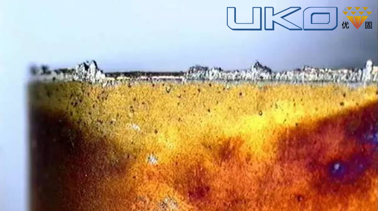
2. Crescent Moon
Crescent is common in high-speed machining operations of iron-based or titanium-based alloys. It belongs to the thermal/chemical problem of blade dissolving into workpiece chips.
The combined effect of diffusion wear and abrasive wear caused crescent craters. When machining base and titanium-based alloys, the heat in the workpiece chips will dissolve and diffuse the components of the cemented carbide into the chips, causing a “crater crater” on the top of the blade. The crescent crater will eventually increase enough to cause the flank face to collapse, deform or even cause rapid flank face wear.
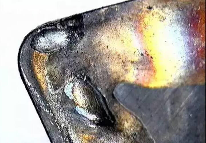
3. Built-up edge

When the fragments of the workpiece are welded to the cutting edge by hot pressing, a built-up edge is generated, which is caused by the chemical affinity, high pressure and high temperature in the cutting area. The built-up edge will eventually fall off, sometimes with the carbide inserts fragments, causing micro-collapse and rapid flank wear.
The built-up edge can be controlled by: increasing cutting speed and feed rate, using nitride (TiN) coated inserts, using cooling fluids reasonably (such as increasing the concentration), and choosing geometry and/or with reduced force insert with smooth surface
4. Slight collapse
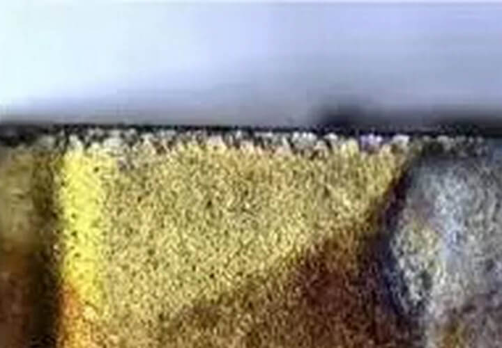
Micro-collapse is caused by unstable mechanical properties, usually caused by weak clamping, poor bearing or spindle wear, hard spots in the processed material or intermittent cutting.
In this failure mode, chips distributed along the cutting edge of the cnc machine inserts are very obvious. Ensuring that the machine is properly clamped, minimizing bending deformation, using abrasive blades, controlling built-up edges, and using tougher blade material grades and/or stronger cutting edge geometry will prevent micro-collapses.
5. Thermomechanical failure
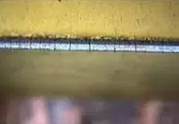
Severe temperature fluctuations and mechanical shocks may cause thermomechanical failure. Stress cracks will form along the blade edge and eventually cause the carbide part of the blade to fall off, which looks somewhat like a micro-collapse.
Thermomechanical failures are most likely to occur in milling operations, and sometimes in intermittent turning of large quantities of parts, end face processing, and processing operations using intermittent coolant. A sign of thermomechanical failure is the appearance of multiple cracks perpendicular to the cutting edge. It is particularly important to identify this failure mode before the onset of micro-collapse.
The following methods can be used to prevent thermomechanical failures: use the coolant correctly, or if you want to completely prevent such failures in the processing process, you can use a more impact-resistant material grade and a groove shape that reduces heat generation and lowers the feed rate.
In addition to normal flank face wear, mechanical fracture can be avoided by correcting all other failure modes. Use more impact-resistant material grades, choose stronger cnc inserts geometry, use thicker blades, reduce feed and/or depth of cut, verify clamping rigidity, and check whether the workpiece contains hard inclusions or is difficult to cut, these They are all effective corrective measures.