The maintenance of the power supply and electrical system is done when installing a USB power supply or drive recorder, or when the blinkers stop working.
For those riders who find circuit testers too difficult to use and have no confidence in their ability to read a circuit diagram, this may be a difficult task.
- A circuit tester will tell you if the circuit is disconnected and if power is coming or not.
- With a clamp meter, current can be measured.
A circuit tester will tell you if the circuit is disconnected and if power is coming or not.
If the ignition system is a kick-start vehicle with a flywheel CDI, the engine will start regardless of battery voltage.
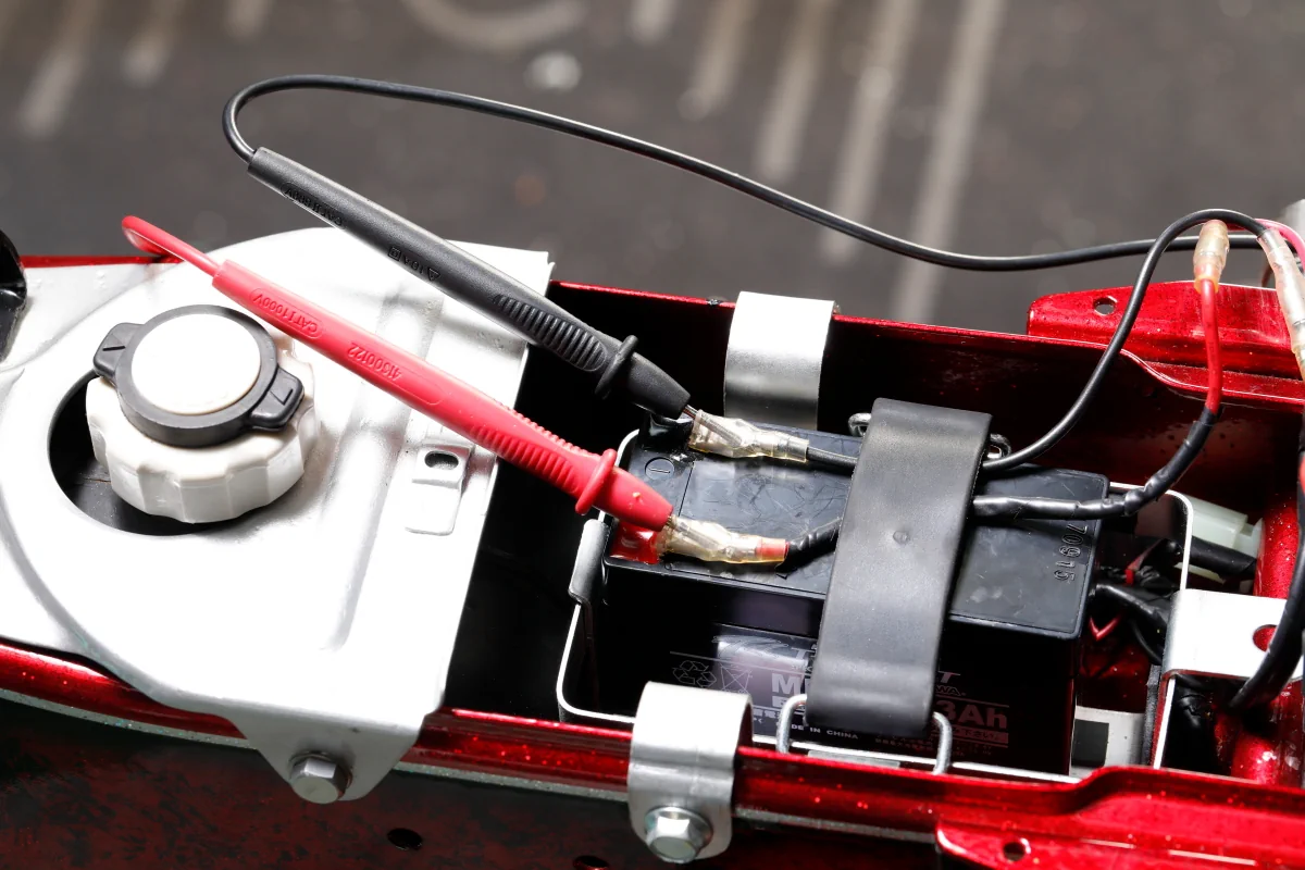
When electrical components that are powered by the battery, such as turn signals, brake lights, and horn, are not working properly, the first thing to do is to measure the battery voltage.
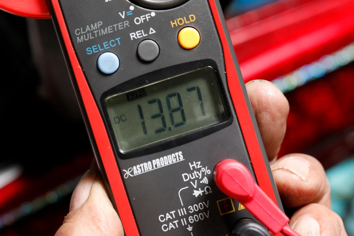
The voltage of a 12V battery rises to around 12.8V when fully charged. If the engine is started and the rpm is increased while measuring the voltage, the voltage should rise to nearly 14V, depending on the battery’s state of charge. If the voltage only rises to the low 12-13V range regardless of engine speed, the battery is either fully charged or there is a problem with the regulated rectifier or alternator.
I turned on the ignition key and pressed the starter button, but the cell motor would not start.
You may guess the battery condition by looking at the neutral light on the indicator or operating the turn signal, and press the starter button again, but it still does not work.
In such cases, the first thing to check is the battery voltage. A lead-acid battery has a voltage of around 12.8V when fully charged, but when the voltage drops to the 11V range, the cell motor starts to spin sluggishly, and starting becomes difficult. If the voltage drops further to 10V or less, the cell motor may not turn even though the magnet switch clicks.
Apart from that, even if the battery voltage is sufficient, there is a possibility that there is a problem somewhere in the starting circuit and voltage is not being applied to the cell motor.
A circuit tester is useful to have in such cases. With the tester, the battery voltage can be visualized to determine whether the battery is the cause of the inability to start or not. Battery voltage is measured in DC voltage mode, but when the alternator generates electricity, it is AC, so the AC voltage mode can be used to measure the rising voltage of the alternator coil (but only when the engine is operating).
Incidentally, in the charging systems of motorcycles and automobiles, alternating current is generated by the alternator, which operates in conjunction with engine rotation, and is converted from AC to DC by a regulated rectifier while being adjusted to a voltage suitable for battery charging.
With a clamp meter, current can be measured.
Even if the battery terminal voltage is 12V or higher, full charge may not be reached if the charging current is low.
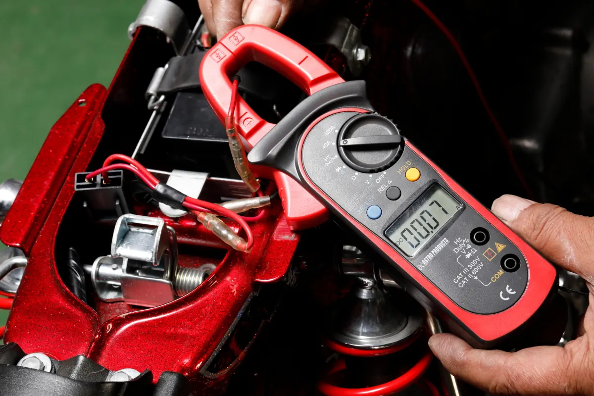
In such cases, a clamp meter is useful. By clamping the battery cord with a sensor and starting the engine, the charge current and discharge current can be measured.
It is normal for the charging current to increase as the engine speed rises, but if the battery is discharged excessively when the headlights, brake lights, turn signals, etc. are activated, it can cause the battery to run down. By looking at the current flow, it is even possible to tell such things.
Some circuit testers can measure large currents flowing through the electrical systems of motorcycles and automobiles. To measure voltage, the tester is connected in parallel to the circuit to be measured. On the other hand, when measuring current, the tester is connected in series with the circuit. This means that the circuit is disconnected at the measurement section and the ammeter is interrupted, which may damage the ammeter in circuits where large currents flow, such as halogen headlights and cell motors.
Such risks can be avoided with a clamp meter.
A clamp meter detects the magnetic field generated when current flows in a circuit and displays it as a current value, allowing measurement simply by clamping the desired wiring with a sensor.
Since there is no need to disconnect the circuit and no current flows inside the tester, even large currents can be measured safely. Although clamp meters are unique among circuit testers, small current, continuity, and resistance values can also be measured with general testers.
However, riders who are not very good at electricity may shy away from using them because they are too difficult to use, just because they have a function switch that allows the selection of a number of measurement modes.